When our customers reach out as a first-time buyer of an Electronic Component Flammability Tester (ECFT), one of the most common questions isn’t about test standards or accuracy—it’s about the installation process. I’ve spent years working with teams ranging from small electronics assembly shops to global automotive component manufacturers, and I can tell you that proper installation is half the battle when it comes to getting reliable, repeatable flammability test results. Too many companies skip a critical step or rush through calibration, only to end up with inconsistent data that leads to costly reworks or compliance failures. As a supplier, my team and I walk every customer through this process, and I’m breaking it down here so you know exactly what to expect when your ECFT arrives. Electronic Component Flammability Tester
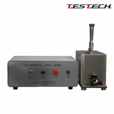
First, let’s get one thing clear: this isn’t a plug-and-play device. It’s a precision instrument designed to simulate real-world ignition scenarios for electronic components, from tiny surface-mount resistors to larger power modules. Cut corners here, and your test results won’t meet IEC 60695-11-10 or UL 94—the two core standards that govern flammability testing for electronics. I once worked with a client in aerospace who tried to save 2 hours during installation and ended up with a failed audit because their test chamber wasn’t level, leading to uneven flame impingement on test specimens. That’s the kind of preventable headache we’re here to avoid.
The first step on installation day is site preparation, and it’s non-negotiable. Before our team even shows up, you need to have a dedicated space for the ECFT that meets four key requirements. First, the room should be free from drafts—even a slight air current can distort the test flame, which is calibrated to 20mm in length for most standard tests. I recommend placing the unit at least 1 meter away from any doors, windows, or HVAC vents. Second, the floor must be level within 0.5 degrees. Most of our testers come with built-in adjustable feet, but if the site is too far out of level, you’ll need to add shims or adjust the room’s flooring beforehand. Third, you need a stable power supply: a dedicated 120V or 240V outlet (depending on your model) with a grounded circuit, no shared power with heavy equipment like soldering irons or wave solder machines. Power fluctuations can damage the flame control module, so we also recommend a surge protector for backup. Fourth, there’s ventilation: the test process produces small amounts of combustion byproducts, so a local exhaust hood with a flow rate of at least 10 CFM should be mounted directly above the tester’s exhaust port. I always remind customers to test their ventilation before our arrival—last year, a automotive client’s exhaust was clogged with solder fumes, and we had to reschedule the installation for a week while they cleaned the ductwork.
Once we arrive, the physical installation is straightforward, but we take our time here. Unboxing the ECFT requires two people, as the main chamber weighs around 80 kg for standard models. We carefully lift it into the designated space, avoiding any impact to the precision flame nozzle or specimen holder. Next, we level the unit using the adjustable feet: we use a digital level tool to check both the front-to-back and side-to-side alignment, making small adjustments until the reading is within the 0.5-degree tolerance. From there, we connect the gas supply. Most ECFT models use either methane or propane, and we strictly recommend using high-purity (99.5% minimum) gas to ensure consistent flame temperature. We attach the gas line to the dedicated inlet on the back of the unit, using a leak-detection solution to check for any seepage—even a tiny leak can cause the flame to flicker during tests. We also connect the exhaust hose to the local ventilation system, ensuring a tight seal to prevent fumes from escaping into the workspace.
The next step is electrical and software setup, which is where most first-time users get confused. We plug the unit into the dedicated power outlet, then turn on the main control panel. The initial boot-up takes about 2 minutes, during which the unit runs a self-diagnostic check: it verifies the flame sensor, gas flow regulator, and temperature probe. If any error codes pop up, we troubleshoot them on the spot—common issues include loose sensor connections from transit, which are easy to fix with a quick re-seat. Once the self-test passes, we connect the ECFT to your local network, either via Ethernet or Wi-Fi, to enable data logging and remote access. This is a useful feature for teams that need to track test results across multiple shifts, as the software automatically saves every flame duration, specimen type, and pass/fail status. We also set up user access permissions, so only authorized personnel can adjust test parameters (like flame height or application time) to prevent accidental data corruption.
Now comes the most critical part: calibration and performance verification. This is what separates a properly installed ECFT from one that’s just sitting in a room. Calibration should be done before the first test run, and we recommend doing it quarterly for ongoing accuracy. First, we calibrate the flame length. Using a precision ruler, we adjust the gas flow until the flame is exactly 20mm long for standard vertical burn tests, or 125mm for horizontal tests per UL 94. Next, we calibrate the flame temperature: we place a K-type thermocouple at the point where the flame impinges on the specimen, running a test to confirm the temperature is 800°C ± 10°C, which is the standard for most component flammability tests. We also verify the gas flow rate, ensuring it’s consistent at 105 mL/min during test runs. To confirm all these settings are correct, we run a performance check using standard test specimens—like the polyethylene strips referenced in IEC 60695-11-10. We run three consecutive tests, checking that the flame extinguishes within the required time and that the results are repeatable (within 5% variance across all three tests). If the results are consistent, we move on to user training; if not, we troubleshoot each component until the calibration is on point.
User training is a step many suppliers skip, but it’s essential for long-term success. Our team spends about 2 hours training your operators, covering everything from basic operation to maintenance and troubleshooting. We walk through how to load specimens into the holder, select the correct test standard, start and stop tests, and access data logs. We also cover common issues: what to do if the flame flickers, how to check for gas leaks, and when to replace the filter in the exhaust system. We provide a printed operation manual and a digital copy, so operators can reference it later, and we offer a 24/7 support line for any after-installation questions. I always emphasize that even the most well-installed ECFT won’t give good results if the operators aren’t trained to use it correctly.
Once installation is complete, we provide a final checklist and a certificate of calibration, which is required for most compliance audits. We also leave a spare set of parts—like replacement nozzles and filters—with instructions on when to swap them out, so you don’t have to wait for a spare part if something goes wrong later. Our team follows up a week after installation to check in, making sure everything is running smoothly and addressing any questions that come up once your operators start using the device.
Over the years, I’ve seen too many companies underestimate how much work goes into a proper ECFT installation. Rushing the site prep, skipping calibration, or skimping on training can lead to hours of wasted testing time, failed audits, and even safety risks from gas leaks. As a supplier, our goal isn’t just to sell you a tester—it’s to make sure it works for you. Every installation we do includes a 1-year warranty, and we offer on-site calibration services for companies that need annual verification.

If you’re in the market for an Electronic Component Flammability Tester, don’t cut corners on the installation process. When you’re ready to discuss your needs, our team is here to walk you through every step, from site preparation to ongoing support. Whether you’re testing components for consumer electronics, automotive systems, or aerospace applications, we’ll help you get a tester that meets your standards and delivers reliable results every time.
Fabric Flammability Tester References
- International Electrotechnical Commission. (2018). IEC 60695-11-10: Fire hazard testing – Part 11-10: Test flames – 50 W vertical flame test method.
- Underwriters Laboratories Inc. (2020). UL 94: Standard for safety of flammability of plastic materials for parts in devices and appliances.
- American Society for Testing and Materials. (2019). ASTM D3828: Standard test method for flash point by small scale closed cup tester.
TESTech Instrument (Suzhou) Technologies
TESTech Instrument (Suzhou) Technologies is one of the most reliable electronic component flammability tester manufacturers and suppliers in China. If you’re going to wholesale durable electronic component flammability tester, welcome to get quotation from our factory. For price consultation, contact us.
Address: 8/F, R&D and Production Workshop No. 5, Jiangsu Guoqian Technology Innovation Industrial Park, 168 Lüliangshan Road, Huqiu District, Suzhou, Jiangsu Province, China
E-mail: sales@testech.com.cn
WebSite: https://www.testechfiretest.com/
