If you’ve ever stood on a production floor watching a roll forming machine shape solar ground mounting structure steel profiles, you know it’s equal parts art and precision. I’m Jake, a technical lead with a solar ground mounting structure roll forming machine supplier, and I’ve spent the last 12 years troubleshooting, tuning, and tweaking these machines for clients from small local solar installers to large utility-scale project teams. One question I get asked at least twice a week is: How do I adjust the machine’s parameters to get consistent, high-quality profiles that fit perfectly with ground mount racking standards? Today, I’m walking through the actual, field-tested steps I share with our clients, no textbook jargon, just real lessons from the floor. Solar Ground Mounting Structure Roll Forming Machine

First, let’s start with why parameters matter—because when you’re producing solar ground mounting structures, a 0.5mm mismatch in a profile’s height, a 1-degree twist, or a burr that’s too sharp can turn a perfectly good steel piling or rail into scrap, or even worse, a safety hazard when it’s installed on a rooftop or ground array. Last year, we worked with a Texas solar installer who was sourcing a cheaper machine overseas; they were adjusting speed off a YouTube tutorial and ended up with 300 unusable Z purlins that couldn’t be bolted to their pre-assembled ground mounting brackets. That’s a $12,000 loss, just from bad parameter tuning. So let’s skip the guesswork and break this down into actionable, sequential steps, starting with pre-adjustment prep.
Before you even touch a knob or input a number, you need to lock in two non-negotiable baseline factors, because adjusting parameters without these is like driving without a compass: the material you’re using and your project’s specific profile specs. For materials, solar ground mounting structures almost always use hot-dip galvanized steel, but not all galvanized steel is the same. I’ve seen clients use 1.2mm thick G90 steel for small residential projects, 2.0mm thick G120 for utility ground mounts, and even pre-painted steel for commercial shade structures. Each of these has different tensile strength, ductility, and springback— that’s the tendency of steel to bounce back after being bent, which is a huge cause of misaligned profiles. If you’re using G90 1.5mm steel vs. G120 2.0mm steel, your bend angle, roll sequence, and speed will change, full stop.
Next, your project’s profile specs. Every solar ground mount has unique profiles: U-channels for pile connections, Z-purlins for panel rails, hat channels for wind bracing, and so on. For example, a standard 10ft Z-purlin for a ground mount might need a flange height of 50mm, web height of 100mm, and a bend radius that avoids cracking the galvanized coating. I always tell clients to pull their engineering drawings first, not just the profile CAD file— those drawings will list tolerances, usually ±0.2mm for critical dimensions, and minimum bend radius requirements to meet solar racking standards (like the ones from the Solar Energy Industries Association, SEIA). Once you have those two baselines, you’re ready to adjust the machine’s core parameters, in this order: roll gap, bend angle, roll speed, and cut length.
Let’s start with roll gap adjustment, the most critical and most commonly misadjusted parameter. The roll gap is the distance between the top and bottom rolls of each forming station— if it’s too loose, your profile will have a wavy edge; if it’s too tight, you’ll scratch the galvanized coating, cause the steel to tear, or even break the roll bearings. For solar ground mounting steel, which is usually pre-galvanized, we use a rule of thumb that’s been tested over decades: set the initial roll gap to match the material’s thickness, then adjust incrementally based on the first test profile. Wait, not exactly— because springback makes that initial gap a bit of a moving target. Let’s say you’re using 1.5mm G90 steel. Your starting point for the first forming station should be 1.52mm, and each subsequent station’s gap is increased by 0.05mm up to the last forming station, which will be around 1.60mm. That accounts for springback, as the steel bounces back slightly after each bend, so the final profile ends up at the exact desired thickness.
But here’s the real trick I share with our clients: don’t rely just on the machine’s digital readout. I always have them cut a 1ft test profile, run it through the last three forming stations, and measure the gap with a digital caliper right at the point where the steel exits the rolls. Last month, a Colorado client called me panicking because their Z-purlins were 0.8mm too wide. We went out to their floor, and their roll gap was set to 1.5mm across all stations, no incremental adjustment. Once we increased the final station gap to 1.6mm, the springback corrected the width, and they were back to producing good profiles in 15 minutes. Also, if you’re working with thinner steel (under 1.2mm), reduce the gap adjustment per station to 0.03mm, not 0.05mm— thinner steel has less ductility, so it springbacks less. For thicker steel (over 2.0mm), you might even need to add 0.1mm to the final gap, because heavier steel has more springback.
Next, bend angle adjustment, which directly ties to the profile’s dimensions and avoids coating damage. Bend angle is the angle the steel is forced to take at each forming station, and it’s programmed into the machine’s controller. For solar ground mount profiles, most bends are between 90 and 180 degrees, but the exact angle is non-negotiable per your engineering specs. The common mistake here is setting the bend angle too high to compensate for springback, which leads to over-bending and cracking the galvanized coating. That’s a huge red flag— cracked coating leads to rust, which is a warranty issue down the line, especially for ground mounts that are exposed to rain, snow, and temperature swings.
How to dial this in? Start with the baseline angle from your profile drawing, then adjust by 0.5 degrees at a time, using the same test profile method. For example, if your spec calls for a 90-degree flange bend, set the initial angle to 89 degrees, run a test profile, and measure the flange with a protractor. If it’s 89.5 degrees, that’s almost perfect; if it’s 88 degrees, add 0.5 degrees. Wait, but what about springback again? For most galvanized steel, a 90-degree bend will spring back by 1 to 2 degrees, so your initial bend should be set 1 to 2 degrees higher than the desired final angle. But here’s the catch: that number changes based on material thickness and grade. I did a side-by-side test last quarter: 1.2mm G90 steel springs back 1.2 degrees, 1.5mm G120 springs back 1.7 degrees, and 2.0mm G185 springs back 2.2 degrees. So if you’re using 1.5mm G120 for your Z-purlin flanges (desired 90 degrees), set the bend angle to 91.7 degrees. The way to confirm is to mark the profile’s bend line, clamp it in a vise after forming, and measure the angle with a digital protractor— that’s more accurate than the machine’s readout, which can be off a degree or two if rolls have worn slightly.
Also, for profiles with multiple bends, like U-channels that have two flanges bent at both ends, adjust each bend station individually. Don’t use a one-size-fits-all angle for all stations. I had a client in Arizona who was adjusting all bends to the same 92 degrees because they thought it would save time, but their U-channels had one flange bent at 91 degrees and the other at 90 degrees, making them impossible to connect to ground piles. After we adjusted each station to its own angle based on test profiles, their fitment rate went from 72% to 100%.
Third, roll speed adjustment, which ties to material flow and surface quality. Roll speed is how fast the machine feeds the steel through the forming stations, and it’s a balance: too fast, and the steel can’t bend properly, leading to uneven edges or surface scratches; too slow, and you’ll have inconsistent production rates, and the steel might develop light rust if it’s sitting on the feed table too long. For solar ground mounting profiles, the ideal speed is between 10 and 20 meters per minute, but again, this depends on material thickness and profile complexity.
Thinner steel (under 1.5mm) can handle faster speeds, up to 20 meters per minute, because it’s more flexible and doesn’t require as much time to bend. Thicker steel (over 2.0mm) needs slower speeds, between 8 and 12 meters per minute, because it’s stiffer and moving too fast will cause the rolls to tug on the steel, leading to misaligned bends. Also, if your profile has tight bend radii, like a hat channel that has a 5mm radius instead of the standard 10mm, slow the speed down by 2-3 meters per minute— tight radii need more time for the steel to form without cracking.
Another common mistake is adjusting speed mid-run to compensate for a bad profile, which makes the problem worse. For example, if a client sees a wavy edge on their profile, they’ll speed up the machine, thinking that will fix it, but it actually makes the wave worse. Instead, slow down, check the roll gap and bend angle, then adjust. Last year, a utility-scale project in New Mexico was running 18 meters per minute and getting 15% scrap from wavey edges. We had them slow to 12 meters per minute, adjust the roll gap by 0.05mm, and the scrap dropped to under 1% overnight. That’s the difference between tuning for the material vs. guessing at speed.
Finally, cut length adjustment, which is the last step in the process, and it’s what turns the continuous formed steel into individual solar ground mount profiles. Cut length is programmed into the machine’s controller, but it’s not as simple as inputting the desired length— you have to account for the “lead-in” and “lead-out” of the forming line, which are the first few feet of steel that don’t meet profile specs, since it takes time for the rolls to settle into their proper positions. For solar ground mounts, we recommend adding a 1ft lead-in at the start of each run and a 6-inch lead-out at the end. That way, when you cut the profiles, you only take good steel, not the material used to get the rolls aligned.
Also, account for the cut’s tolerance. Most ground mount profiles need a ±1mm length tolerance to fit with brackets. So if you need a 10ft (3048mm) profile, don’t input exactly 3048mm; input 3047mm, because the cut blade has a slight amount of movement, and adjusting the cut length slightly will bring you right to the desired size. For profiles that are longer than 20ft (common for utility ground mounts), add an extra 1mm to the input length to account for minor stretching that happens as the steel is fed through the machine over long distances.
Wait, but what about when you’re switching between different profile types? Like going from Z-purlins to U-channels? The parameter adjustment doesn’t just stop at switching rolls— you have to re-calibrate all four parameters, not just change the profile in the controller. I’ve seen clients think that switching rolls is the only change needed, but their bend angles and roll gaps are still set for Z-purlins, leading to bad U-channels. My rule is: every time you switch rolls for a new profile, do a full test run of 5 profiles, measure each critical dimension, adjust each parameter in order (roll gap first, then bend angle, then speed, then cut length), and then run a final test batch of 20 to confirm consistency.
I also can’t skip two maintenance parameters that people often overlook, because bad machine condition skews all your adjustments. First, roll alignment: if the forming rolls are misaligned (from wear, or a recent roll change), your profiles will twist no matter how good your parameters are. We recommend checking roll alignment once a month with a straight edge— if there’s a gap between the straight edge and the top roll, adjust the roll bearings until the gap is under 0.1mm. Second, lubrication: solar ground mounting steel is galvanized, so you don’t want to use heavy lubricant that leaves residue, but a light, food-grade lubricant for the rolls will prevent scratches and reduce springback. Too much lubricant makes the steel slip in the rolls, leading to inconsistent dimensions, too little causes friction and surface damage.
Let’s wrap this up with a real example of how this works in practice. Last month, we had a client in Florida who was tasked with producing 5,000 Z-purlins for a 2MW ground mount project. Their initial setup was wrong: roll gap set to 1.5mm across all stations, bend angles set to identical numbers, speed at 22 meters per minute. They were getting 20% scrap, and their profiles weren’t fitting with their ground mount brackets. We walked through our step-by-step process: first, confirmed they were using 1.5mm G120 galvanized steel, so adjusted the initial roll gap to 1.52mm, incrementally increasing to 1.60mm at the last station. Then, calculated springback for 1.5mm G120: 1.7 degrees, so set the bend angle to 91.7 degrees. Slowed the speed to 12 meters per minute, adjusted the cut length to 3047mm for 10ft profiles with a 1ft lead-in. After that, their scrap dropped to 0.8%, and all 5,000 profiles fit perfectly with no rework.
At the end of the day, adjusting a solar ground mounting structure roll forming machine isn’t about mastering a secret code—it’s about being methodical, testing, and tuning based on your specific materials and project specs. If you rush through it, you’ll end up with scrap and delays, but if you take the time to lock in the basics first, you’ll get consistent, high-quality profiles that meet all solar racking standards.
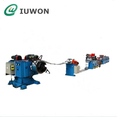
If you’re a solar ground mount installer or project manager looking to optimize your roll forming line, or if you need help calibrating your machine for your upcoming project, our team of technical experts is here to walk you through every step, from pre-adjustment prep to ongoing maintenance. We’ve supported projects across the U.S. and internationally, from small residential arrays to 100MW utility ground mounts, and we know how critical consistent profiles are to keeping your project on time and on budget. Reach out to our team to discuss your specific needs.
Purlin Roll Forming Machine References
Roll Forming Technology for Structural Applications, Society of Manufacturing Engineers, 2019.
Solar Ground Mount Racking Design Standards, Solar Energy Industries Association (SEIA), 2022.
Galvanized Steel Forming Best Practices, American Iron and Steel Institute (AISI), 2021.
Hanghzou IUWON Technology Co., Ltd.
Address: No.755, Xintangtou Village, Xinjie Street, Xiaoshan District, Hangzhou, Zhejiang
E-mail: sales@iuwon.com
WebSite: https://www.iuwonforming.com/
